Stresses in the Hammer Beam Truss
Hi there
I am soon to be taking a course in hammer beam frames, and I am trying to get my head around the stresses in the frame/truss (below the collar tie).
I am wondering if one structural job of the hammer beam (assumed as the elements below the collar tie – hammer beam, vertical post on top and bracing members) ; is to work as a ‘stiff’ beam which simply reduces the lateral deflection/thrust in the top chord/rafter and subsequently reduces the thrust and moment in the top of the wall/buttress/supporting posts.
many thanks for any insight into the fascinating world of timber trusses. Also i wonder if there are any good texts on analysis of timber frames you could recommend.
Many thanks
Ben
Background in Engineering, UK.
Hi Ben, thanks for the question!
Hammer beam (HB) trusses are certainly an engineering marvel, and are one of the most open and regal truss types out there.
Here at VTW we occasionally create traditional HB trusses, but we often work with and design modified HB trusses. Modified HB trusses have more intermediate bracing and webbing and a lower collar tie, but can eliminate the need for buttressing in other parts of the structure. The additional members can help resolve the tension present along the bottom of the truss, unlike a traditional truss. Unless the structure has the ability to resist the outward thrust present at the bottom of the HB truss, the modified HB truss is the way to go. We usually use the hammer beam itself as a robust bending member, as the hammer post (vertical) and brace (into the post) go into significant compression.
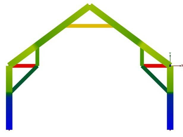
Here is an axial load diagram of a traditional HB truss (green->blue is compression, orange->red is tension):
In this instance, the hammer beams are in tension attempting to resolve the compression that is developed in the brace, and is then kicking into the post. Unfortunately with this design, the truss is likely unable to adequately resolve the tension at the eave, and will need a positive connection at each eave with enough stiffness to prevent the lateral deflection.
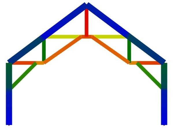
In contrast, here is an axial load diagram of a modified HB truss (green->blue is compression, orange->red is tension):
This truss behaves much more like an actual truss, with the ability to have a tension line along the hammer beam, up into the web, down the other side and/or up into the king post. These trusses can almost always be self-contained, not requiring any additional framing to be supported.
With both designs, the tensile forces are often too significant for traditional joinery methods (a single mortise and tenon with a 1” peg can usually take ~800 lbs tension). To resolve those forces, we often use steel joinery that can be hidden on tops of the webs and HBs, and sent up through the king post.
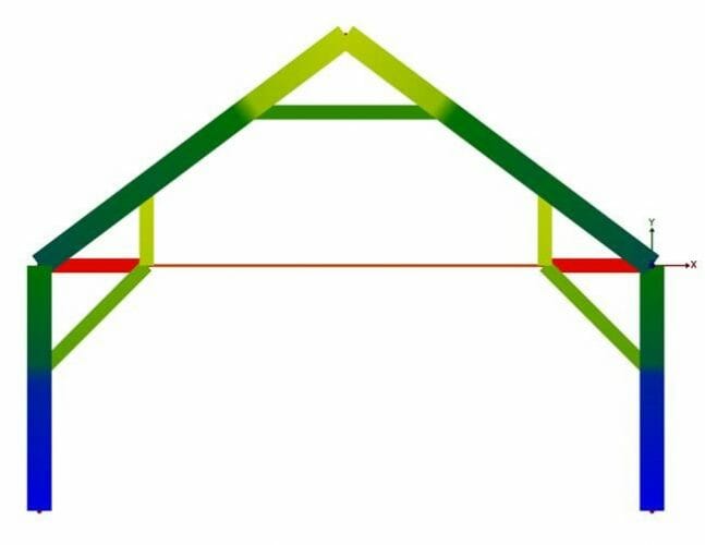
The last option is a traditional HB truss with a bottom chord, like VTWs logo! This is often a great compromise, keeping the appearance of a traditional HB truss while resolving the tension either in a solid member or in a steel tension tie.
Here is an axial load diagram of that possibility:
This design often results in the lowest volume of timber and steel to achieve the same span, making it the most economical. The modified hammer beam can sometimes match in value, it depends on the wood species, span, and spacing of the trusses.
If you would like to see examples of HB trusses (traditional and modified) we post most of our previous work on our website, here are links for both:
https://www.vermonttimberworks.com/blog/hammer-time/
https://www.vermonttimberworks.com/our-work/timber-trusses/modified-hammer-beam/
For additional information, the Timber Framers Guild has a great website with a bunch of resources, here is the link for their website:
https://www.tfguild.org/about-the-guild
Thank you,
Matthew McGinnis, EIT


