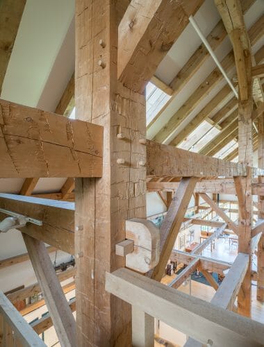
How Do I Account for the Capital in Calculating the Capacity of the Main Beam?
I have an existing warehouse building with 2×10 floor joists @ 20″ oc spanning 16′ supported on 12×12 timbers spanning 24′-6″ bearing on a 12×12 capital x 6′ long on a 10×10 post.
How do I account for the capital in calculating the capacity of the main beam?
Hi Tim, thank you for your question.
When I am first designing structures I usually air conservatively and take the beams effective length as its full length, neglecting the capital and/or bearing on its supports. This gets me to a beam size that should be more than sufficient, and if needed I can possibly downsize a dimension later on in the design process.
That being said, when I want to sharpen my pencil I calculate the effective length as the clear distance between the supports, plus ½ of each bearing surface. Here’s what that will look like:
Assuming the 24’6” is the ctr-ctr spacing of the posts, when I would first check the capacity I would use that as my effective length.
When sharpening my pencil on the design, I would use (24.5’ – 3’*2) = 18.5’ as the clear distance, then adding back in ½ of the bearing length on each side: 18.5’+(1/2*3’)*2 = 21.5’, or 21’6”.
You would then use the new effective length in your bending stress calculation, which at 20” o/c loading is more or less evenly distributed, so you could use:
Mmax = (1/8)*w*L^2, where w is the linear loads in plf, and L is your effective beam length.
In timber design you then find the actual bending stress by dividing the maximum moment by the section modulus, or S= (1/6)*b*h^2, where b is the beams width and h is the beams height. You’ll need to convert your maximum moment into lb*in from lb*ft, and then that will give you your actual bending stress. As long as that is smaller than the allowable bending stress provided for your timber species (with applicable adjustment values) in the AWC-NDS Supplement table 4D, you’ll be good to go.
Hope this helps!
Matthew McGinnis, EIT
Junior Timber Frame Engineer

